
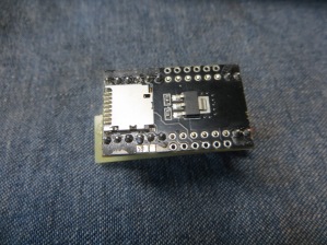
I’ve always wanted to build a versatile Teensy-based device for use in physical security penetration testing. I’ve seen Irongeek’s device, and Mike Czumak’s dongle, but neither of these had an SD card, and only had a 4 of 5 position DIP switch. I liked the capability of Kautilya but it didn’t seem to use a dynamic payload using DIp switches. I didn’t want to have to re-program the device if a payload didn’t work. Also I had just received a Teensy 3.6 with a MB of flash (The Teensy 3.2 only has 256KB). I wanted to have more flexibility, so I ordered several 4-position DIP switches, and a WIZ820+SD card adaptor. I followed directions and attached the adapter to the Teensy 3.2 to get this:
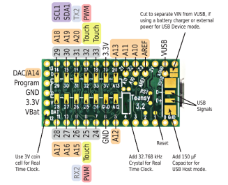
I wanted to leave the top alone, in case I decided to add Ethernet to it. So how do I attach an 8-position DIP switch? Hmm. I knew I had to avoid using the 4,9,10,11,12,13 pins. I pondered this a bit, and stared at the bottom of the Teensy 3.2 for a while:
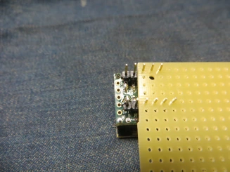
Those pads in the middle of the board looked like they would work. But how do I attach the DIP switches? I had some perfboard and some right-angle headers. So with a little bit of thinking, I had a plan. I first cut a 6-piece header, and a 5-piece header. Then I used some perfboard to hold the headers into position, and I soldered one end:
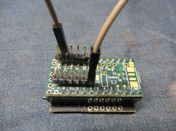
I repeated this for the other end. Now I had some headers attached to digital pins 24-33 and ground. I then tested the headers for connectivity with my test program, using a female-to-female jumper:
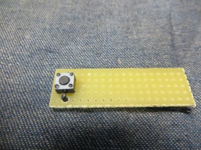
Once I knew these were solidly connected I could proceed. I first planed to just have 2 4-position DIP switches, but I thought that it would be more convenient if I added a reset button. So I first did a dry-run layout of the pieces on the perfboard:
The hookup wire I had was 20-gauge solid wire (I prefer solid for electronics that doesn’t move), and frankly the wire w/insulation was thicker than I wanted. It made the assembly tight. I also had to drill some larger holes in the perfboard so the wires would pass-through. But in the end it worked. I first attached the reset button:
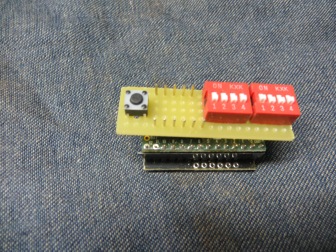
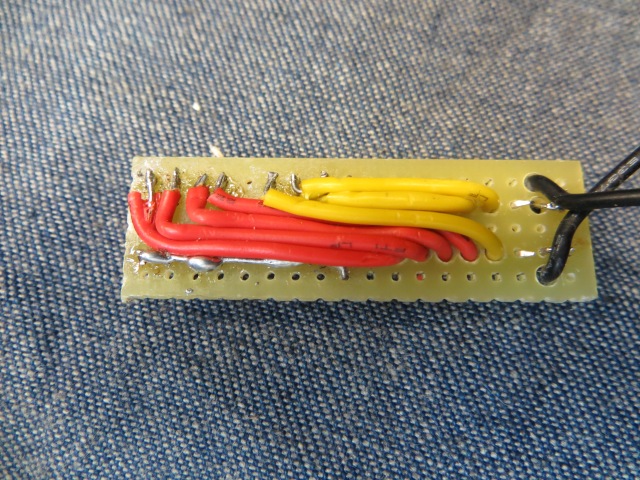
I attached the DIP switches, and connected all of them on one side (to be connected to ground) . These are the bottom pins in this diagram:
I attached one side of the reset button to the ground side of the board. The other pin was going to be attached to the tiny reset bad on the bottom of the board. This posed a problem because this wire had to be flexible. I cannibalized a wire from a breadboard jumper wire, attached it from the switch to the reset pad, with some heat shrink on the connection:
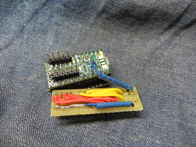
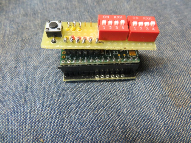
I zapped the heatshrink, and assembled the two boards. I soldered the wires to the headers, and connected the ground pin header to the ground wire on the perfboard. It’s not quite as snug as I’d like and you can see it doesn’t quite lay flat. Next time I need some 22-gauge hookup wire. That would make the assembly easier.
I used the following Arduino program to test everything a second time.
const unsigned int dip1 = 24;
const unsigned int dip2 = 25;
const unsigned int dip3 = 26;
const unsigned int dip4 = 27;
const unsigned int dip5 = 28;
const unsigned int dip6 = 29;
const unsigned int dip7 = 30;
const unsigned int dip8 = 31;
const unsigned int dip9 = 32;
const unsigned int dip10 = 33;

unsigned int dips = 0;

void initDip(void) {
    pinMode(dip1, INPUT_PULLUP);
    pinMode(dip2, INPUT_PULLUP);
    pinMode(dip3, INPUT_PULLUP);
    pinMode(dip4, INPUT_PULLUP);
    pinMode(dip5, INPUT_PULLUP);
    pinMode(dip6, INPUT_PULLUP);
    pinMode(dip7, INPUT_PULLUP);
    pinMode(dip8, INPUT_PULLUP);
    pinMode(dip9, INPUT_PULLUP);
    pinMode(dip10, INPUT_PULLUP);

}
void setup(void) {
    Serial.begin(9600);
    initDip();
}

void loop(void) {
  dips=0;
  delay(500);

  !digitalReadFast(dip1) && (dips+=1);
  !digitalReadFast(dip2) && (dips+=2);
  !digitalReadFast(dip3) && (dips+=4);
  !digitalReadFast(dip4) && (dips+=8);
  !digitalReadFast(dip5) && (dips+=16);
  !digitalReadFast(dip6) && (dips+=32);
  !digitalReadFast(dip7) && (dips+=64);
  !digitalReadFast(dip8) && (dips+=128);
  !digitalReadFast(dip9) && (dips+=256);
  !digitalReadFast(dip10) && (dips+=512);

  if (dips>0) {
     Keyboard.print("dips: ");
     Keyboard.println(dips);
   }
}
Now I can have up to 256 different payloads – assuming they can fit on the chip + SD card. So let’s see how this goes. If I run out of flash, I could try to do the same thing for the Teensy 3.6 chip. And there are many ways to optimize the memory usage of the chip with an external SD card.
